On real roads
A directional T is a three-leg interchange, the kind usually built where one highway begins or ends at another.1 None of its ramps is a loop: the right turns take direct ramps, and each left turn a semi-direct one, which normally exits to the right first and reverses direction before it joins the other highway.2
When freeways of real length were built in the late 1930s and early 1940s, the cloverleaf, the diamond and the trumpet were the main interchange forms.3 By the time the Interstate system began, in 1956, interchanges were sorted into a few basic types, and the three-leg ones were the trumpet, the directional T and the Y.3,4
In the 1950s some system interchanges got exits and entrances on the left as well as the right.3 Experience and research showed that left exits have more crashes than right ones, and by the 1990s exits and entrances all on the right were generally accepted practice.3,4 On a directional T the left turns normally exit on the right as well.2
The Massachusetts design guide finds the directional T best suited where both left turns are fairly heavy; where every turn is heavy, it points to a fully directional form.1 A semi-direct ramp carries about 1,200 to 1,500 vehicles an hour, where a loop is limited to 800 to 1,200.2 The same guide counts the directional T among the costliest three-leg types, as its centre needs several structures for three levels of traffic, and like every three-leg interchange it is very hard to expand to four legs later.1
Where to see one
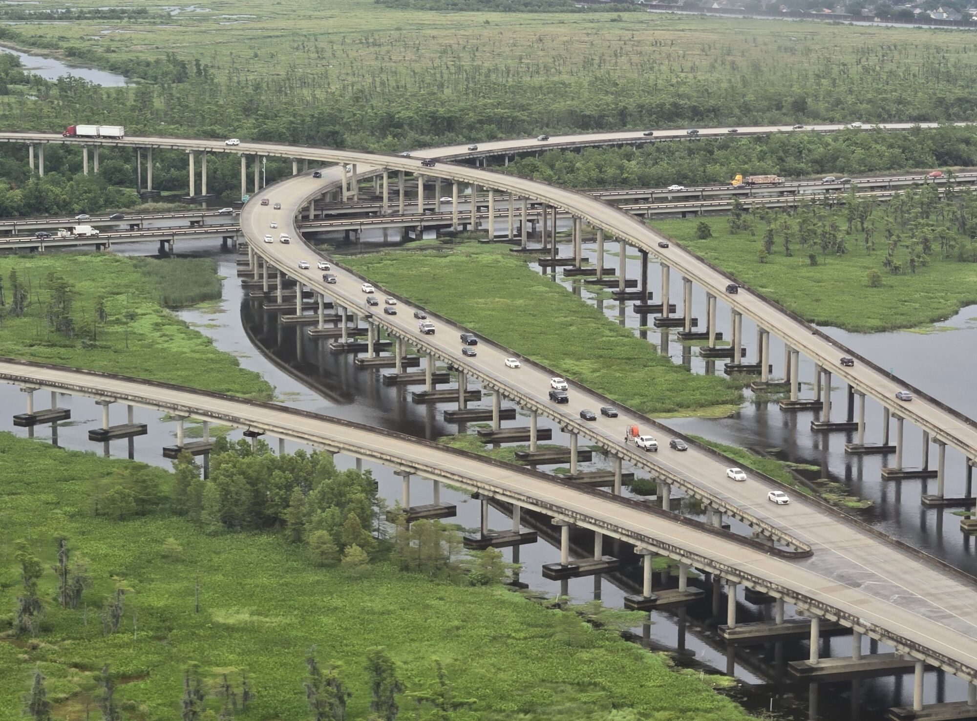
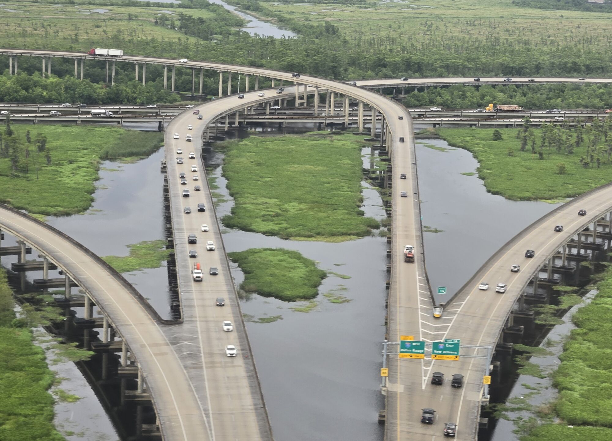
The I-310 and I-10 interchange over the LaBranche Wetlands, St. Charles Parish, Louisiana, 2026. Spatms, CC BY-SA 4.0, source, cropped, shown in greyscale I-10 at I-310, St. Charles Parish, Louisiana, US. Map
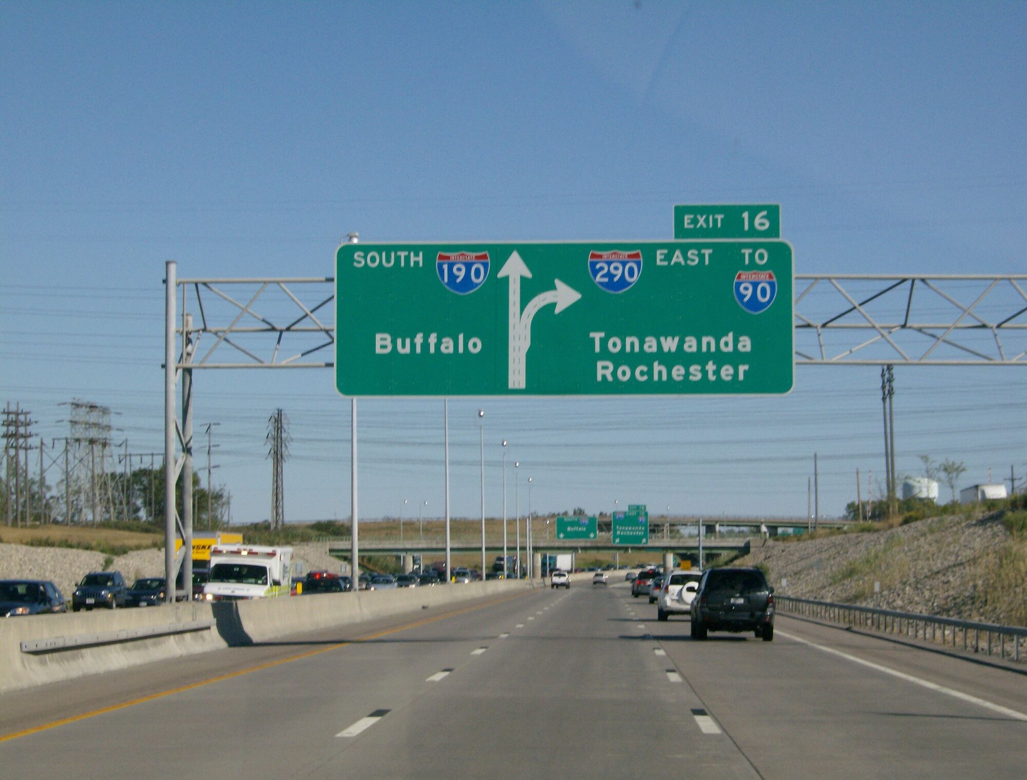
Interstate 190 southbound at Interstate 290 in Tonawanda, New York, 2007. The semi-directional T interchange that connects the two is in the background. TwinsMetsFan, CC BY-SA 3.0, source, cropped, shown in greyscale I-190 at I-290, Tonawanda, New York, US. Map
The Roadform adaptation
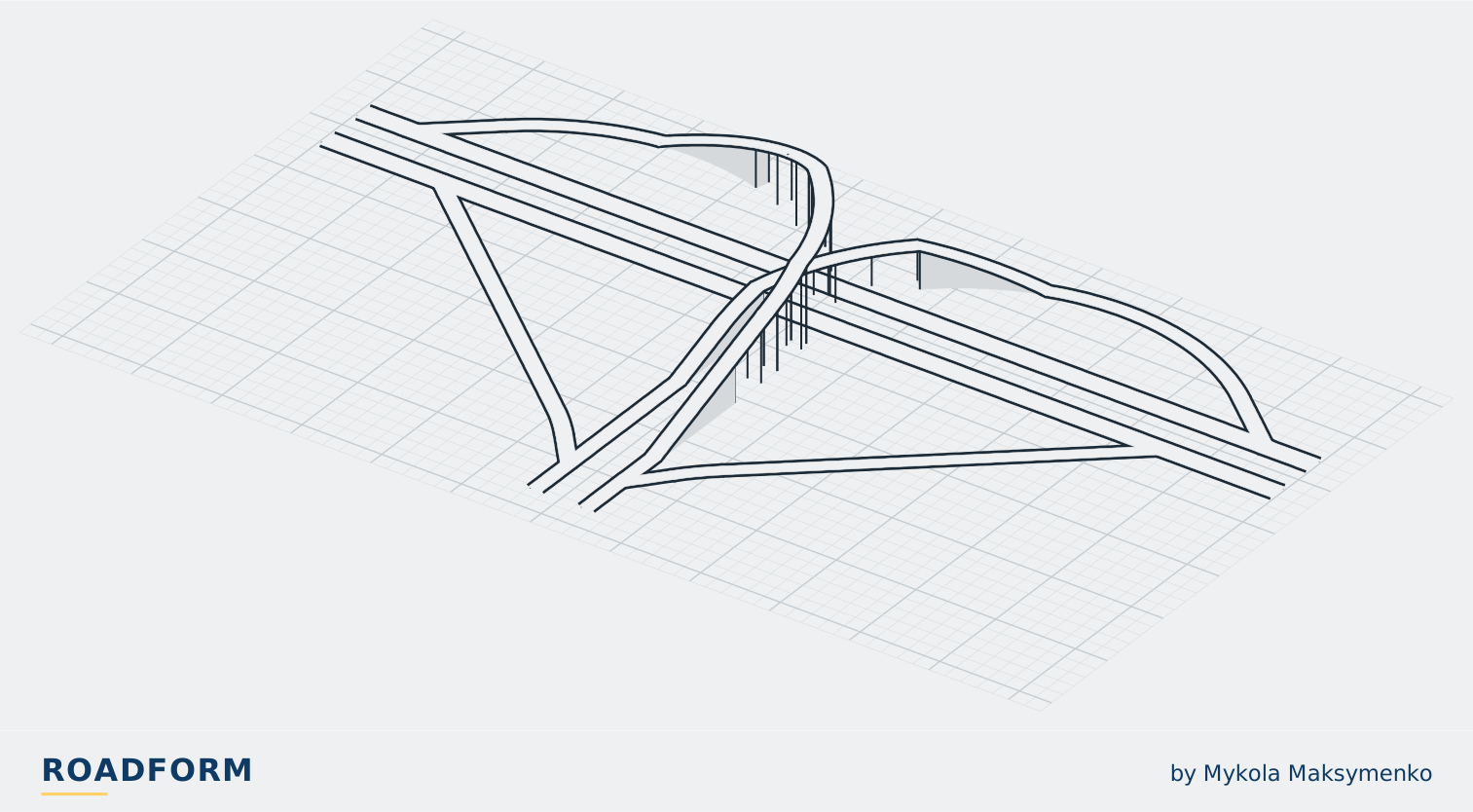
In Roadform
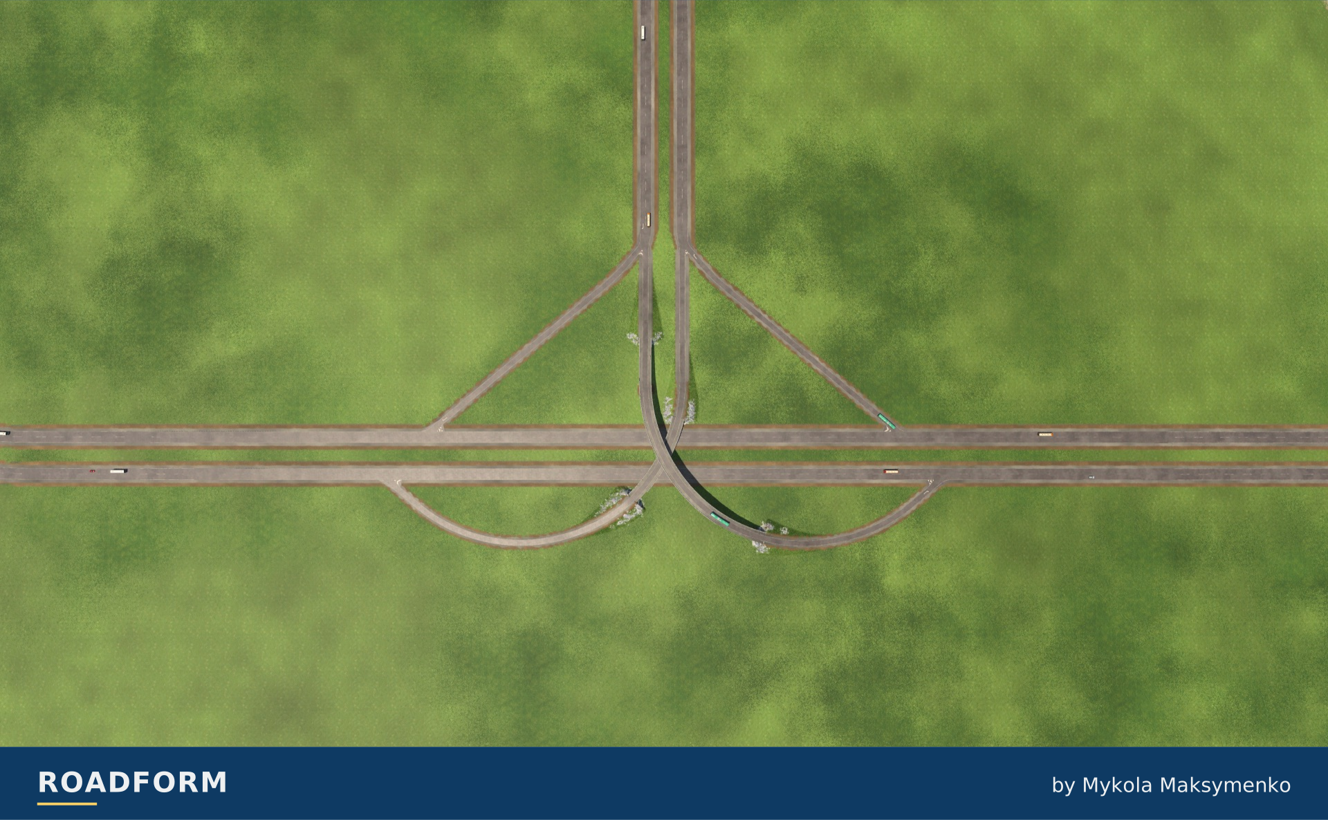
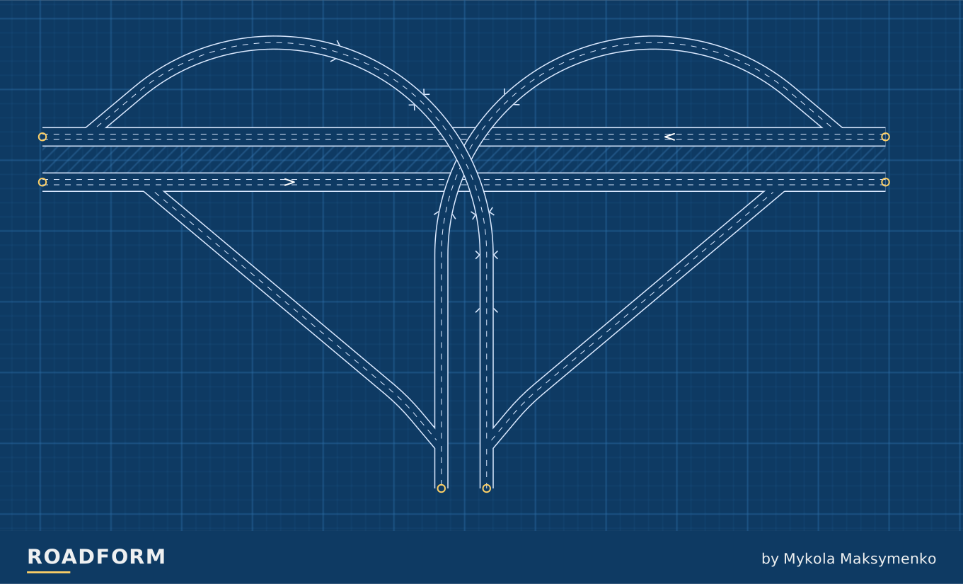
A highway ends at another; each turn has its own ramp, and the two left turns cross over the highway at 8 and 16 m.
Reading the connections
TF3 · M · Traffic side: Right.
Scale and capacity
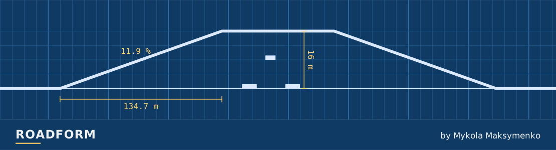
Size changes the road widths and the space the layout needs. The guide below uses the default arrangement. The layout reserves room for wider roads.
| Layout | Width × depth | Highest road | Lanes per direction |
|---|---|---|---|
| S | 551 × 292 m | 16 m | Highway: 2 Ramps: 1 |
| M | 596 × 315 m | 16 m | Highway: 2 / 3 Ramps: 2 |
| L | 641 × 324 m | 16 m | Highway: 3 Ramps: 2 |
Sources and credits
- Project Development and Design Guide, Chapter 7 Interchanges, Massachusetts Department of Transportation. www.mass.gov
- Roadway Design Manual, Chapter 10 Interchanges, South Carolina Department of Transportation, 2021. www.scdot.org
- Freeway and Interchange Design: A Historical Perspective, J. P. Leisch, Transportation Research Record 1385, Transportation Research Board, 1993. onlinepubs.trb.org
- Evolution of Interchange Design in North America, J. P. Leisch and J. Morrall, Transportation Association of Canada, 2014. www.tac-atc.ca
Real-world photo credits accompany each image. Roadform figures and measurements use Transport Fever 3.